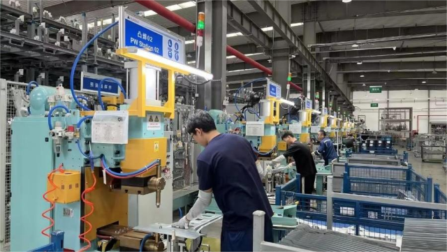
A robotic welding cell can repeat the same programmed motion thousands of times, yet repetition alone does not guarantee consistent welds. Electrode wear, fixture movement, unstable current, poor part fit-up, and incorrect sequencing can gradually turn a well-tuned process into a source of defects.
Troubleshooting robotic resistance welding therefore requires more than checking whether the robot follows its programmed path. Engineers need to examine the interaction between robot positioning, welding force, electrical output, electrodes, tooling, and production conditions.
When the Robot Reaches the Right Point but the Weld Is Still Wrong
One of the first diagnostic traps is assuming that correct robot coordinates mean correct weld positioning. The robot may reach its programmed location while the actual sheet stack has shifted because of fixture wear, dimensional variation, loose locating components, or changes in part fit-up.
A displaced electrode changes the effective contact area and current path. The result can be an irregular weld, inconsistent nugget formation, or visible marks outside the intended location. Resistance welding troubleshooting guidance identifies electrode alignment, tip condition, and workpiece cleanliness among factors that can contribute to abnormal weld geometry.
The solution should begin at the mechanical interface. Inspect fixture repeatability, locating pins, electrode alignment, gun mounting, and part seating before changing the weld schedule. Increasing current to compensate for a mechanically unstable process can mask the real cause rather than remove it.
Electrode Wear Can Quietly Change the Process
Electrodes are exposed to repeated heating, force, and contact with the workpiece. Their working faces can gradually change shape, increasing the contact area and altering current density. Once that happens, a previously stable welding schedule may no longer produce the same thermal conditions.
TWI recommends appropriate electrode dressing and notes that current stepping can also be used to compensate for progressive electrode wear. It also emphasizes establishing a welding condition with sufficient tolerance to wear before weld quality is affected.
A useful maintenance strategy is therefore tied to actual production behavior rather than an arbitrary replacement interval. Electrode condition, tip diameter, alignment, cooling, and weld-count trends can be reviewed together.
For high-volume resistance welding applications, this is particularly relevant because a gradual change across many cycles may be harder to detect than a sudden equipment failure.
Unstable Current Is Not Always a Controller Problem
Current variation naturally attracts attention because welding current has a direct relationship with heat generation. Resistance welding produces heat through electrical resistance while current and weld time are controlled during the process.
However, an unexpected welding result does not automatically mean that the controller is malfunctioning. Secondary connections, electrode contact, material condition, cable configuration, and mechanical force can all influence the electrical conditions at the weld.
A more disciplined diagnosis starts by measuring the actual welding output and comparing it with the programmed condition. If the current is stable but the weld result varies, attention should move toward electrode condition, material fit-up, force, or heat dissipation.
Modern controllers can also provide additional process-control functions. Sunke’s published MFDC controller information describes primary and secondary current-control modes as well as real-time monitoring and diagnostic functions.
Force, Timing, and Robot Motion Must Agree
The robot, welding gun, and controller operate as one sequence. A weld should not be treated as an isolated current pulse because electrode approach, contact, squeeze, welding, hold, and release all affect the process.
Insufficient electrode force can contribute to unstable contact and expulsion, while excessive force can alter contact resistance and deformation. Welding current and time must also be appropriate for the material and joint configuration.
Robot motion creates another variable. If the gun reaches the programmed position before the workpiece has settled or begins welding before the intended force condition is established, the electrical schedule may be correct while the physical process is not.
Their automotive welding solutions include robot welding-tong applications, demonstrating why controller behavior and robot-cell coordination need to be considered together rather than specified as completely separate systems.
Why Problems Return After the First Adjustment
A recurring production problem often indicates that the initial correction addressed the symptom rather than the process condition behind it. For example, increasing current may temporarily compensate for an enlarging electrode face, but it does not restore the original contact geometry.
Material variation can create a similar situation. Surface condition, coating, thickness, and fit-up can influence the resistance and heat distribution of the joint. A process that has little operating margin may therefore become unstable when incoming material changes slightly.
Monitoring can make these patterns easier to identify. Rather than evaluating only finished parts, engineers can track welding current, voltage, force, or other available process variables and compare them against established conditions.
That approach is especially valuable across demanding resistance welding applications, where a small process shift repeated over hundreds of cycles can create substantial rework before the underlying cause becomes obvious.
Building a More Stable Robotic Welding Cell
Reliable automation starts with treating the welding cell as a complete process rather than a robot with a welding attachment. Mechanical positioning, electrode maintenance, current control, force, cooling, monitoring, and production data all influence the final result.
Sunke‘s application portfolio covers automotive BIW welding as well as other automated and precision resistance-welding scenarios, illustrating the range of process conditions that equipment must accommodate.
For engineers troubleshooting robotic resistance welding, the most effective sequence is usually to verify the physical weld location first, inspect electrode and fixture conditions, measure electrical output, confirm force and timing, and then review longer-term process trends. Parameter changes should come after those checks, not before them.
That method reduces the risk of continuously adjusting the welding schedule to compensate for mechanical or equipment problems. Stable robotic production ultimately depends on keeping the robot, welding power source, tooling, electrodes, and process controls working from the same set of verified conditions.